Axiom 49 Keyboard Repair
I recently repaired a MIDI keyboard which has been causing me trouble for a long while. This was my first go at doing electronic board repair with surface mount components, and it went well!
See the LCD display flicker on and off as the unit resets itself at random moments:
This model is pretty old now, and many of these units suffered a problem dubbed the “blue screen of death”. This relates to how the LCD would go dead and the blue backlight was the only sign of life.
I found a walkthrough of this repair in this excellent YouTube video. Fortunately I was able to follow along with that repair video and replicate the steps, both testing to find the problem and also the fix.
Apparently, this model often suffers a failure in the supervisor chip, used to reset the main microcontroller (MCU) when it’s first turned on. Here it is, circled in red:
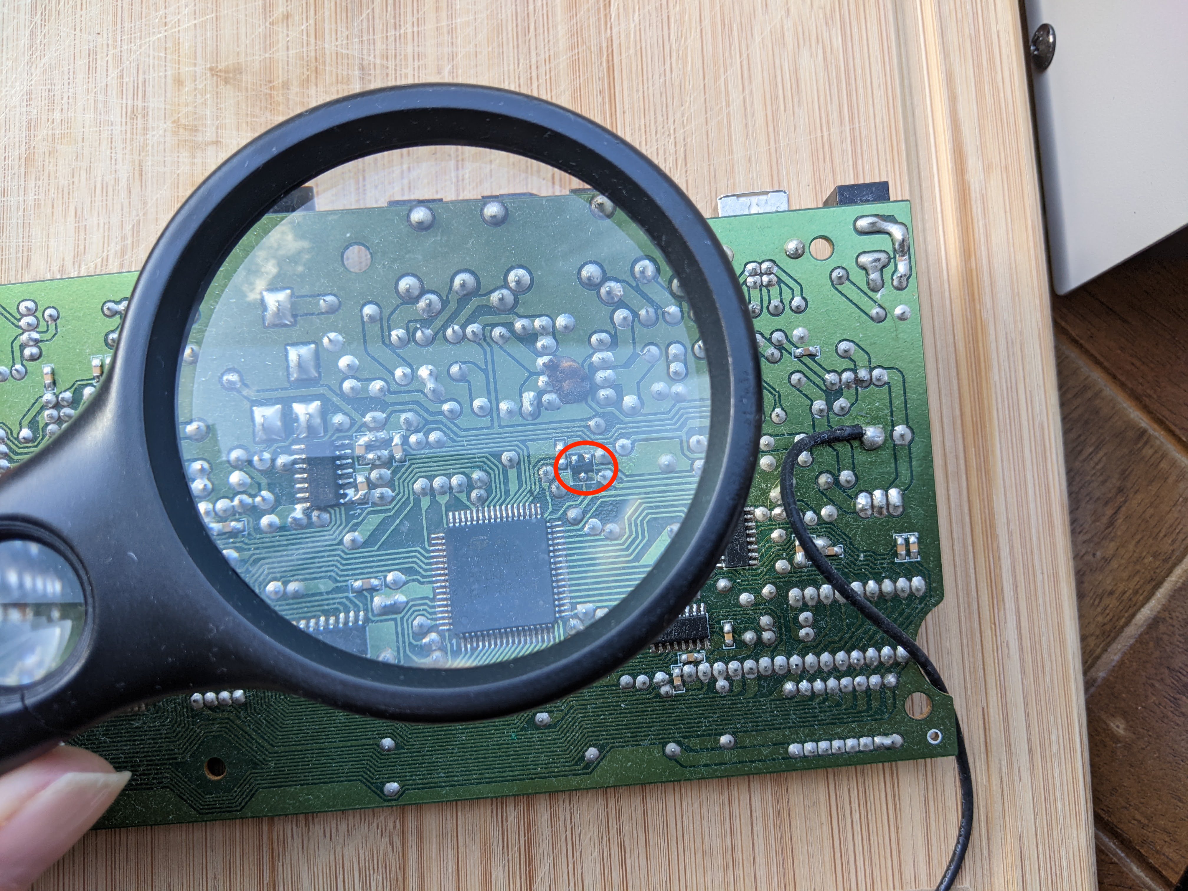
It’s a simple three-pin part, so is relatively easy to work with and understand.
What does this chip do? The main microcontroller (MCU) (below-left of the circled area) needs to be started up in a controlled way, only when the power to the keyboard has stabilised. This is normally done by applying a voltage to the reset pin of the chip.
It turns out MCUs can be quite fussy about exactly when this reset signal is applied. In this case, if this signal comes too early, the MCU hasn’t fully started up and it won’t work. Additionally in my case, I think the reset signal was going low at random times, causing the LCD to blink out since it was no longer under control by the MCU.
My case was very similar to the linked YouTube video - the reset signal was happening too early - but mine was highly sporadic. Sometimes it would be fine, and would then flicker off and on during operation, leading to stuck notes while playing as MIDI events would naturally be dropped. So it was hard to confirm I had the same issue (faulty reset behaviour), as I couldn’t reproduce it predictably.
I ended up pulling out the main board, setting up an oscilloscope, and switching the keyboard off and on many times until I finally confirmed the issue. The hardest thing here was holding the oscilloscope probes in the right position while switching the keyboard off and on. Additionally I needed a mirror to see the LCD display with the unit opened up, as this was the only way to confirm the problem had occurred!
Finally I got the evidence I needed to commence the repair. Here’s a couple of traces showing the difference between normal operation, and when the problem occurs. The yellow trace is the voltage at the main power rail, so it goes high when I switch on the power. The blue trace is the voltage at the reset pin (connected directly to the reset chip). Under normal circumstances the second trace should go high at least 100ms after the power rail goes high:
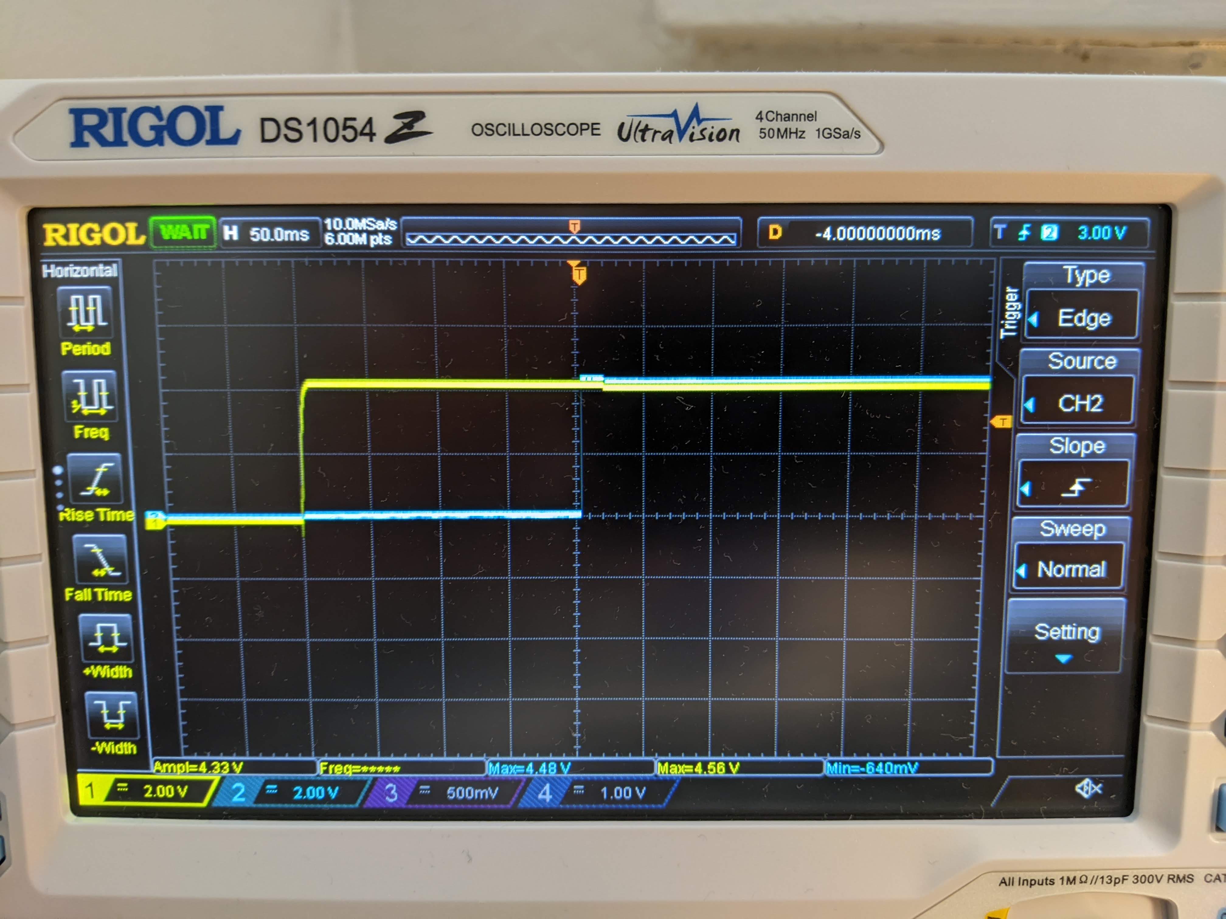
Each horizontal division is 50ms, so 4 squares mean 200ms elapsed between power on, and the reset signal. All good.
And here’s a trace when the problem occurred (LCD never initialised):
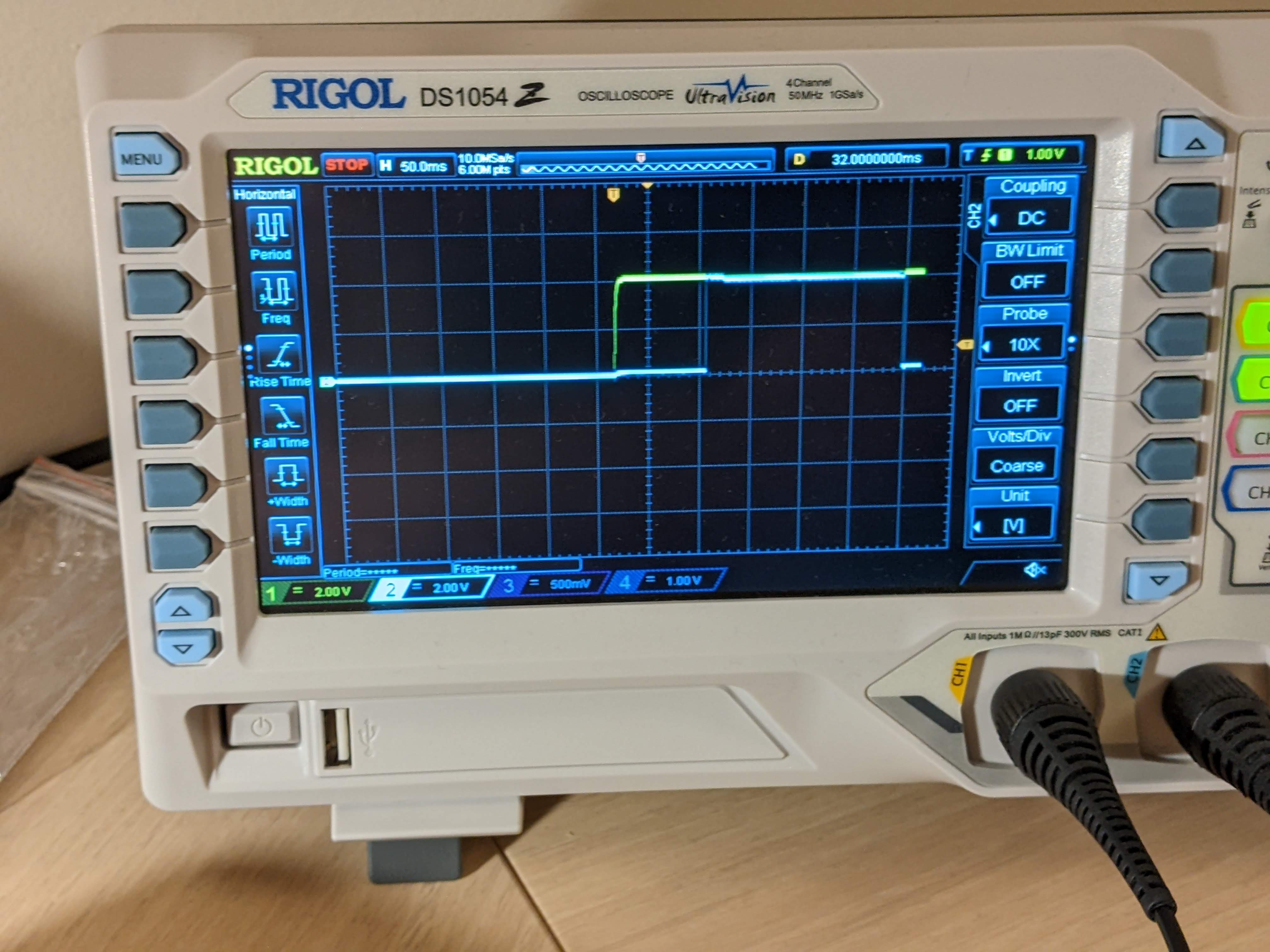
Here, the reset signal is coming less than 100ms after the power goes on.
This change in timing behaviour did correlate with the fault, so it this does point to the reset chip being the root cause of the issue. I couldn’t find clarity on the expected timing in the datasheet for the MCU (which happens to be a ST92T163L), so I couldn’t independently verify this for myself.
So on to the fix. The linked video suggested to remove the reset chip, and replace it with a resistor and capacitor. The values of these would be chosen to create the necessary rise time in voltage. I thought I’d try to order a replacement chip instead, as hopefully it’d be easier to solder in place of the removed faulty chip.
I ordered three TCM809 chips from Digikey, along with a flux pen. I got hold of the excellent Quick 857-DW hot air station to remove the faulty chip and to place the new one.
Fortunately the job was very easy in the end. The hot air station made easy work of the removal (especially as this unit has leaded solder), and the new chip flowed nicely into place with the existing solder (along with plenty of flux).
The hardest part was placing the new chip on the existing pads - the lightest touch with a pair of tweezers would easily nudge this tiny chip away, and it would easily turn upside down.
One thing I had to cautious of was ordering the correct part - active low, and in a SOT-23 package to match the footprint of the removed chip. The same chip was also available in a SC-70 package which is smaller, and wouldn’t have matched the existing pads. I’ve started using my micrometer a lot more often recently for making measurements on these kinds of projects - these two are 1 millimeter different in size.
Looking back, this project would have been a lot easier if I’d replaced the part without worrying about confirming the issue. Since my issue didn’t quite manifest the same way I wanted to be sure, and also it was interesting to follow along with that video and trace the fault myself.